- Flex PCB Blog
- PCB Assembly Blog
- FPC Research Blog
- Preparation of FPC based on ultrasonic spraying method_4_Experimental Results
- Preparation of FPC based on ultrasonic spraying method_3_Experimental Procedure
- Preparation of FPC based on ultrasonic spraying method_2_Experimental Platform and Principle
- Preparation of FPC based on ultrasonic spraying method_1_abstract
- Research on Layout Design Method of Ultra-thin FPC_4_Analysis of Layout Design Methods
- Research on Layout Design Method of Ultra-thin FPC_3_Analysis of Layout Design Methods
- Research on Layout Design Method of Ultra-thin FPC_2_Analysis of Layout Design Methods
- Research on Layout Design Method of Ultra-thin FPC_1_introduction
- Research progress on polyimide FPC_2_the field of FPC
- Research progress on polyimide FPC_1_Introduction
- Analysis of Vibration Characteristics of FPCBs _4_Summary
- Analysis of Vibration Characteristics of FPCBs _3_Finite Element Analysis
- Analysis of Vibration Characteristics of FPCBs _2_Theory of Vibration Analysis
- Analysis of Vibration Characteristics of FPCBs Under Random Vibration_1_Introduction
- Design Methods for FPCBs_5_Practical Application
- Design Methods for FPCBs_4_Electrical Circuit Design and Examples
- Design Methods for FPCBs_3_Structure Design Method and Examples
- Design Methods for FPCBs_2_Component Selection Methodology and Examples.
- Research on Design Methods for FPCBs
- Application of MPW technique for FPCBs _4_Summary
- Application of MPW technique for FPCBs_3_Experimental results
- Application of MPW technique for FPCBs_2_Experimental setup
- Application of MPW technique for FPCBs_1_Principle of MPW
- Application of FPCB in PC motherboards_4_ Results and discussion
- Application of FPCB in PC motherboards_3_ Numerical analysis
- Application of FPCB in PC_2_ Experimentation
- Application of FPCB in PC motherboards
- A Bus Planning Algorithm for FPC Design _4_Experimental result
- A Bus Planning Algorithm for FPC Design _3_Proposed Algorithm
- A Bus Planning Algorithm for FPC Design _2_Preliminaries
- A Bus Planning Algorithm for FPC Design _1_Introduction
Analysis of Vibration Characteristics of FPCBs _3_Finite Element Analysis
3. Finite Element Analysis of Flexible Circuit Boards
In this paper, the vibration characteristics of flexible circuit boards are analyzed based on the finite element method and corresponding finite element analysis software, and the dynamic performance of the established flexible circuit board is evaluated.
COMSOL Multiphysics is a commercial software based on the finite element solution method, which excels in multi-field coupling analysis and calculation. It achieves numerical simulation and modeling by solving partial differential equations. In this paper, the built-in drawing tools of COMSOL are used to create the model, with the substrate measuring 0.3m in length, 0.2m in width, and 1.5mm in thickness. The substrate is attached with aluminum-based heat dissipation devices, silicon-based and acrylic plastic electronic components, as shown in the three-dimensional model in Figure 1.
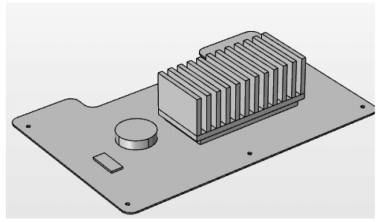
Figure 1 Flexible Circuit Board Structure
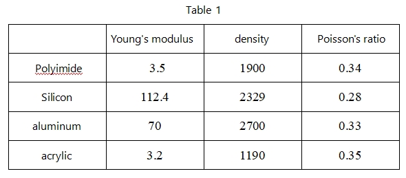
The material properties required for the Structural Mechanics module mainly include Young's modulus, density, and Poisson's ratio. The model constructed in this paper consists mainly of the substrate and attached electronic components. The substrate material is polyimide, and the materials for the attached electronic components are silicon and gold, metallic aluminum, acrylic plastic, and capacitor materials. The material properties are shown in Table 1.
The flexible structure adopts a free tetrahedral mesh to divide the model. To obtain more accurate calculation results in the polyimide substrate area, the mesh in this region is finer, while the rest of the mesh is coarser. The circuit board is in a boundary fixed constraint state, and calculations are performed under two random vibration conditions to analyze its dynamic characteristics. Figure 2 shows the input random vibration PSD spectrum.
Figure 2 Random Vibration PSD Spectrum
In this paper, the first 12 modes of modal shapes of the flexible structure are calculated, and the first 4 modes are selected for typical analysis. Figures 3 to 6 show the first 4 modal shapes of the flexible circuit board, with the first 4 global natural frequencies of the model being 57Hz, 97Hz, 106Hz, and 141Hz, respectively. From the modal shapes, it can be seen that the vibrations are mainly concentrated on the polyimide substrate area, hence the flexible circuit board with various electronic components attached can be considered as a flat-like structure.
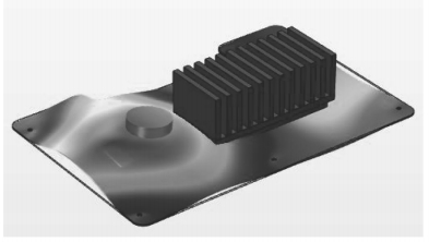
Figure 3 First Mode Shape Diagram
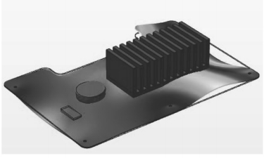
Figure 4 Second Mode Shape Diagram
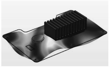
Figure 5 Third Mode Shape Diagram
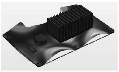
Figure 6 Fourth Mode Shape Diagram
In this paper, a time-domain analysis of the flexible circuit board is performed, calculating the time-domain response within 50ms. Figure 7 shows the global stress-time curve of the circuit board, and Figure 8 shows the global strain-time curve of the circuit board.
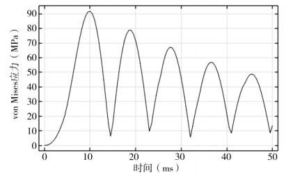
Figure 7 Global Stress-Time Curve of the Circuit Board
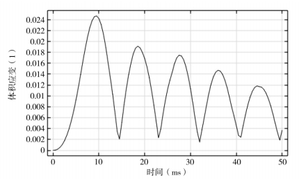
Figure 8 Global Strain-Time Curve of the Circuit Board
From the figures, it can be seen that the response peaks occur at 9ms, 18ms, 27ms, 36ms, and 45ms. To further clarify the response distribution characteristics of the flexible circuit board, this paper organizes the stress and strain nephograms of the structure at 9ms, 18ms, 27ms, 36ms, and 45ms. Figures 9 to 13 show the stress distribution diagrams of the structure at 9ms, 18ms, 27ms, 36ms, and 45ms, respectively, and Figures 14 to 18 show the corresponding strain nephograms. It can be observed from the figures that the flexible circuit board exhibits specific stress and strain distributions at 9ms, 18ms, 27ms, 36ms, and 45ms, indicating the intricate dynamic behavior of the structure under random vibration.At 45ms, the stress and strain are mainly concentrated at the fixed constraints and areas with larger equivalent masses.
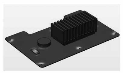
Figure 9 Stress Nephogram at 9ms
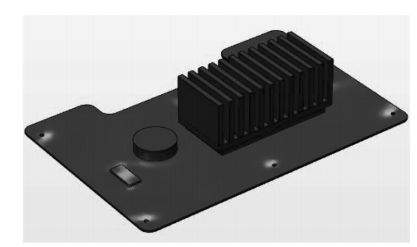
Figure10 Stress Nephogram at 18ms
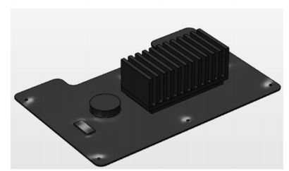
Figure 11 Stress Nephogram at 27ms
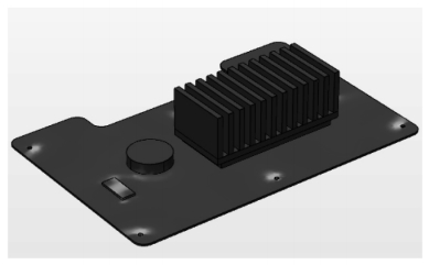
Figure 12 Stress Nephogram at 36ms
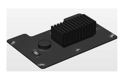
Figure 13 Stress Nephogram at 45ms
From this analysis, it can be concluded that under long-term dynamic load excitation, the flexible circuit board is prone to delamination damage due to high stress and strain at the fixed constraints and areas with larger equivalent masses, affecting the safety of the structure. To avoid electronic component damage and failure caused by stress concentration, this paper suggests that reasonable layout of electronic components can prevent damage caused by excessive stress. Combining the results of modal analysis, it is found that the stress values near the heat sink area are relatively small, and the vibration localization phenomenon in this region is not prominent. Therefore, arranging the attached electronic components as close as possible to the heat sink area will provide better protection.
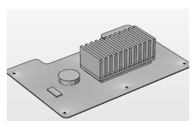
Figure 14 Strain Nephogram at 9ms
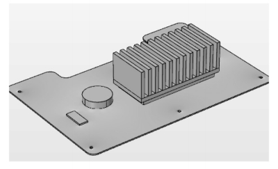
Figure 15 Strain Nephogram at 18ms
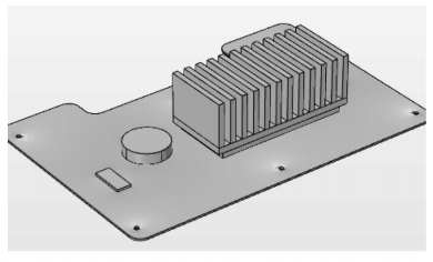
Figure 16 Strain Nephogram at 27ms
Figure 17 Strain Nephogram at 36ms
Figure 18 Strain Nephogram at 45ms


